DC Mini Circuit Breaker
 JB-63 2P
 JB-63 4P
JB-63
>> Download PDF (0.80MB)
IEC 60947-2, EN60947-2, GB 14048.2
-
The JB is a DC circuit breaker dedicated to multi string photovoltaic installations.
This circuit breaker is designed to protect the cables located between each string of photovoltaic modules and the photovoltaic inverter against overloads and short circuits (see application diagram).
Combined with a switch , the JB will be installed in a string PV protection enclosure at the end of each string of photovoltaic modules.
It can be locked (by a padlocking device) in OFF position as a safety measure for removal of the PV inverter.
Since a fault current can flow in the reverse direction to the operating current, the JB can detect and protect against any bidirectional current.
To ensure the safety of the installation, it is necessary, depending on the various types of application, to combine the JB with:
■ a residual current device at the AC end
■ a fault passage detector (insulation monitoring device) at the DC end
■ an earth protection circuit breaker at the DC end
In all cases, fast action on site will be required to clear the fault (protection not ensured in the event of a double fault).
JB is not polarity sensitive: (+) and (-) wires can inversed without any risk.
The JB is: delivered with three inter-pole barrier to provide increased isolation distance between two adjacent connectors.
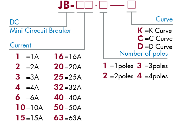
Meaning and classification models
Main characteristics
| Operating Voltage (Ue) | 1P=250 V DC, 2P=500 V DC 3P=750 V DC, 4P=1000 V DC |
| Rated insulation voltage (Ui) | 1,000 VDC |
| Breaking capacity (Icu) | 10 kA |
| Impulse voltage (Uimp) | 4 kA |
| Electrical connection | By the bottom for In and Out |
| Number of poles | 1P, 2P, 3P, 4P |
| Standards | IEC 60947-2 EN 60947-2 |
Technical data
-
■ Position contact indication - suitability for isolation according to IEC/EN 60947-2 standard.
■ The presence of the green strip guarantees physical opening of the contacts and allows operations to be performed on the downstream circuit in complete safety.
■ Increased product service life thanks to fast closing independent of the speed of actuation of the toggle.
■ Pre-wired product: Input / Output on the same side.
| Rated service breaking capacity (Ics) | 100 % of the Icu | |
| Endurance (O-C) | Electrical | 1,500 cycles (where L/R=2 ms) |
| Mechanical | 20, 000 cycles | |
| Mechanical | 20, 000 cycles | |
| Degree of pollution | 2 | |
| Category | A (no delay in accordance with IEC / EN 60947-2 standards) | |
| Degree of protection (IEC 60529) |
IP40 | |
| Tropicalisation | Relative humidity: 95 % at 55°C in accordance with IEC 60068-2 and GB 14048.2 standards |
|
| Temperature | Operating | -25°C to 70 °C |
| Storage | -40°C to 85°C | |
Wiring diagram

Overall and Mounting Dimensioned Chart

