CZ-3 Compact Prewired Limit Switch


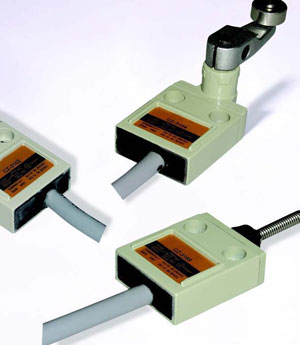
Features
>> Download PDF (364KB)
Ratings
| Rated Voltage (V) | Noninductive Load (A) | Inductive Load (A) | ||||||
| Resistance Load | Lamp Load | Inductive Load | Motor Load | |||||
| NC | NO | NC | NO | NC | NO | NC | NO | |
| 125VAC 250VAC |
5(0.1) 3 |
1.5 1 |
0.7 0.5 |
3 2 |
2 1.5 |
1.3 0.8 |
||
| 8VDC 14VDC 30VDC 125VDC 250VDC |
5(0.1) 5(0.1) 4(0.1) 0.4 0.2 |
2 2 2 0.05 0.03 |
5 4 3 0.4 0.2 |
4 4 3 0.4 0.2 |
3 3 3 0.05 0.03 |
|||
Characteristics
Rating |
5A 125V, 3A 250VAC |
| Operating speed | 1mm-1m/s |
| Operating frequency | Mechanical: 120 operations/min. |
| Electrical: 30 operations/min. | |
| Contact resistance | 15mΩ max. (initial value) |
| Insulation resistance | 100mΩ min. (at 500VDC) |
| Dielectric strength | 1000VAC, 50/60HZ for 1 minute between terminals of the same polarity |
| 1500VAC, 50/60 HZ for 1 minute between currentcarrying and non-current-carrying metal parts |
|
| 1500VAC, 50/60 HZ for 1 minute between each terminal and ground | |
| Vibration frequency | 10-55HZ,1.5mm double amplitude |
| Shock | Mechanical: 1, 000m/Sec2 (about 100G'S) Electrical: 500m/Sec2 (about 50G'S) |
| Ambient temperature | -10℃ to +70℃ |
| Humidity | <95% RH |
| Life | Mechanical: 10,000,000 operations min. Electrical: 200,000 operations min. |
| Degree of protection | IEC: IP 67 |
| Weight | Approx. 360g (cable length 3m) |
| Approx. 540g (cable length 5m) |
Operating characteristics
| Models | CZ-3101 | CZ-3102 | CZ-3103 | CZ-3104 | CZ-3110 | CZ-3111 | CZ-3112 | CZ-3113 | CZ-3169 |
| OF Max. | 1200gf (11.77N) |
1200g f(11.77N) |
1200gf (11.77N) |
580gf (5.69N) |
1200gf (11.77N) |
1800gf (17.65N) |
1800gf (17.65N) |
1800gf (17.65N) |
150gf (1.47N) |
| RF Min. | 450gf (4.41N) |
450gf (4.41N) |
450gf (4.41N) |
150gf (1.47N) |
450gf (4.41N) |
450gf (4.41N) |
450gf (4.41N) |
450gf (4.41N) |
- |
| PT Max. | 1.8mm | 1.8mm | 1.8mm | 25 | 1.8mm | 1.8mm | 1.8mm | 1.8mm | 15 º |
| OT Min. | 3mm | 3mm | 3mm | 40 | 3mm | 3mm | 3mm | 3mm | - |
| MD Max. | 0.2mm | 0.2mm | 0.2mm | 3 | 0.2mm | 0.2mm | 0.2mm | 0.2mm | - |
| OP | 15.7 ± 1mm | 28.5 ±1mm | 28.5 ±1mm | - | 28.5± 1mm | 24.9 ±1mm | 34.3 ±1mm | 34.3 ±1mm | - |
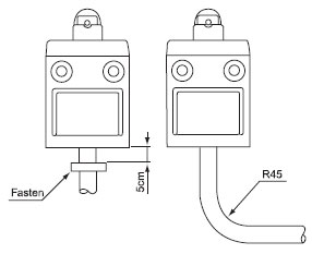
| Fastening of the switch cable The switch bodies are filled with resin for sealing purposes. To avoid stressing the cable and switch body, fasten the switch at 5 cm or farther away from the switch body, should the wire be bent, the bending radius shall be at least 45mm. |
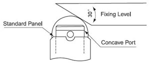
Installation The service life and accuracy of switches will be effected bythe shape of actuator operation frequency & over travel. So theangular of the fixing level should be about 30, the surface finishof the fixing level should be over, the hardness is from HV400~500.When installing, the position of the concave part should be abovethe standard panel |
|||||||||
 |
 |
|||||||||
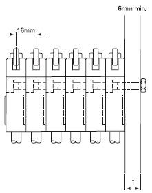
| Contact types | Switch bank mounting A maximum of six switches may be mounted together as a switch bank.During the installation,the convex part of the switch back.The mounting panel shall be 6mm or thicker. |
|||||||||
 |
 |
|||||||||
| Mounting Recommended tightening torque according to the follwing form. |
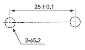
Mounting holes Mount the switch body to a rigid mounting panel using two M5 screws. |
|||||||||
|
 |
